|
MSR-2000
MOTOROLA REPEATER
WELCOME TO A REPEATER PROJECT FROM

 Updated 12/10/2015
C73KSB1106CDX S/N 582PJN1057
Allot of information here, be patient
while loading.
|
For the Micor conversion web-site click
here.
This is a HOW
TO article on a Motorola MSR-2000 repeater, 100 watt
continuous duty.
Editors note:
You want the low frequency model for amateur radio. TLD2601A (132-150.8)
100 watt model.
20 of us hams from the K7CC B.A.R.T.
group got together and purchased this as a gift for WD7F
John Slusser in Tucson AZ. He is the trustee of 146.940 and has given allot to
us hams that have used his system. Along with the MSR-2000
repeater we purchased a
CAT-250 controller, a RLS-1000 remote switch and a
VA3TO
Echolink interface.
This project was started by myself K7IOU, but could not have happened without
the support of all the generous hams who are listed on the Certificate below. I
would like to give special thanks to Craig Walker KD7TXO. Without his support
and technical expertise this project would not have been attempted. And a very
big thank you to Skipp May of Radio Wrench. Skipp has given us allot of advise
on this project including crystal install, set up, squelch gate card conversion
and controller adjustment. This project was researched for weeks and
not much was found on the internet about converting this repeater to amateur radio. I
hope this web site
helps you if you decide to take on this project. We will try to document the
complete project here along with trial, tribulations, references, pictures and links.
When we first got the repeater it wouldn't
transmit. After a all night session until 2 AM Craig and I got her transmitting. We
found several things wrong. The 2 outer pins (grounds) on the R1 Audio card were
bent over. Several dirty pots. Then the repeater wouldn't act as a
repeater. I removed the cards one by one and checked their jumper
settings. Some were off or not connected. After this repair Craig and I
re-checked it with the Marconi. Craig said "its
a boy". IT WAS WORKING!
After the above we suggest
you pull all cards, clean pots, inspect jumpers per settings in
the manual. Connect to a dummy load with a s.w.r. / power meter. Then test. The
above will save you much time and also let you configure the HAL-2000 (MSR-2000)
to your specs. I.E. repeater, with or without tones, and so on. There is a RF
sensor in the back of the repeater tied to the TX alarm. The coax comes out of
the P.A. and feeds into it. Then out the back of the SO-239. Ours was tripping
the alarm and we were having to reset the TX alarm. This was due to the bent
pins (grounds). This protects your system. As it did with ours.
Credit to Richard from BRO-COMM
USA, he was
going to send us another repeater for a replacement as this one was suppose to
have been fully bench tested and it was not. (We think what happened was the
repeater we received had a different serial number than the invoice, so we got
the wrong one). But with a some work its now operational. So all is
well. Thank you Richard for your expertise. Richard has a good reputation for
standing behind his product. Skipp (below) bought 4 of these from Richard and he
came highly recommended. Richard's Ebay reputation is excellent with over 300+
feedback @ 100% positive at this time of writing.
Update;
with reservations I must admit that I had several problems in dealing with
Richard. Several emails went unanswered. Even though Richard was going to send
another repeater I offered to try to repair this one which we did. Richard was
helpful in this repair by faxing the jumper pin outs of several cards. So we
saved Richard $180 in shipping costs. I asked him if he had a remote base and
desk microphone. He said he would send one. They didn't arrive and Richard
hasn't responded to my emails. Maybe there is a explanation for this but I don't
know what it is.
Richard did a fine job packing the repeater for
shipping. He also sent some extra modules. One to replace one that was marked
defective. Also a Morse ID module with our repeater call burned into it. After
hearing horror stories from others that purchased a MSR2000 elsewhere I would
order from Richard again. I heard from a ham that ordered one from the Phoenix
area and it was shipped with only cardboard around the repeater. Well you can
guess the condition it arrived in. The repeaters Richard sells are the Canadian
model of the MSR2000. We noticed that most of the module numbers don't match the
ones published in the manuals. But the pin outs were the same. The exception was
the Morse ID module as it wasn't in the manual at all. Again thanks to Skipp for
finding it for us on his micro fish and providing us with PDF files.
Crystals. Where to
order? Most places we checked takes about 3
weeks to make the crystals plus shipping time. We
decided since we are amateurs we would
install them ourselves. There
are several crystal mfg.'s but they had minimum orders of $50 plus $10
shipping or were just more expensive. Some people just pull the filter elements and send
them in as a unit. Bomar was $35 each and
ICM was $49.95 each plus shipping.
Two other places which I can highly recommend are; Channel Element
Headquarters 1-800-237-9654 (call them as they stock crystals in elements. Give
them the element number and frequency and they will check stock), very reasonable. And
NKX, Inc. 1814 Hancock St. Gretna, La. 70053 Talk to Pam at
504-361-5525. (Pricing includes elements, 3-4 day processing, and will give $5
credit for each element mailed in). NKX is the one to order from!!!!
Editors note: We had a
very big problem with West Crystal
in Canada so I won't recommend them. They messed up our mailing address so
it was returned by the U.S. postal service for insufficient address. I asked
them to re-ship them UPS so I could track them. They told me they didn't have a
UPS account. But could ship them UPS if I gave them my account #. I told them to
ship them UPS ground or standard. They sent them 2nd day air and didn't mark the
weight on the envelope. So they defaulted to 30 lbs. @ $129.00 for shipping. I
called them about this error and was told "I am tired of dealing with this.
We are not going to send you new crystals." And then hung up the telephone
on me. Since this was shipped on my account I am liable for the shipping. I
spent hours on the phone with UPS trying to resolve this issue. So this
taught me a lesson. Never give out your UPS account number and I
will Not deal with this company ever again. I did not find them to
be honest. I report you decide. de k7iou
A little about our repeater group.
K7CC
B.A.R.T. Group Web page of the Border
Amateur Radio Team in Tucson, AZ. BART
is a group of Tucson Amateurs who operate and
control the 146.940 VHF Repeater current located in N.E. Tucson near the
crossing of Harrison Road and Snyder Road.
To be more exact: N
32.17.65 W 110.47.48
Grid Square: DM42OH
Power at XMtr: 90 watts
Antenna: Ringo Ranger ~50'
BART, and the repeater as well, was
rejuvenated to include some new users of the 146.940 machine. Bart Paine,
K7CC, started BART many years ago, and he is the last of the ORIGINAL members.
You can be a member too. Just use the .94 repeater. No dues, no fees
to pay.
She arrives..  The unveiling, it had 1 1/2" of hard foam on all sides for shipping. UPS
requires it for over 80#. Shipping weight 124#.
The unveiling, it had 1 1/2" of hard foam on all sides for shipping. UPS
requires it for over 80#. Shipping weight 124#.  Ah.. On the bench..
  Surprise!
  Just kidding
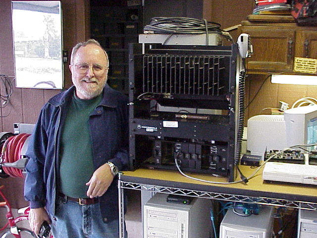
  Recognition..
 Looking at it..
Smile!  The Marconi..
 SWR/Power..
 Receiver test
  Remote switch..
 Proper test box
  Squelch gate module
  Squelch gate jumper settings
 Cat-250 controller
  Rack mount
I made the enclosures for the remote switch and the controller. I cut out the
back of the metal boxes (courtesy of n7geg's estate) for the plugs and drilled
the covers for access to adjustments. The rack mount was made from an old rack
shelf. The repeater had 2 screws in the front which I removed, drilled and
installed a reducing stud. Tightened with a nut on the backside and a wing nut
on the front for easy removal of the rack mount.
Installed rack mount  Cables made by WD7F
How to install your crystals per Skipp.
Tell them you want crystals for the MSR-2000 Channel Elements type KXN-1086
and KXN-1088 units. You might have different numbers on your channel
elements, simply supply those numbers to them along with the desired
frequencies. The crystals arrive and you replace them into the channel element.
The metal cover slides off the channel element, once you lift/raise the two
shell crimp detents at the bottom. Note there is insulation plastic
underneath and how it came out of the shell. I desolder the old crystals with
"solder wick", also known as Chem-wick desoldering braid and wedge
lift them out of the element with a very small flat blade screw driver. I
bend the new crystal leads a soft 90 degree turn and place them into the old
crystal position, check the level and spacing, then solder and cut the excess
lead off. Replace the plastic insulators in place, noting there is a ground tab
that needs to fit into a notch on the insulator and touch the metal shell. Put
the shell on and press the crimps back down into place. I type up a paper
label and stick it on the element (with the new frequency) and place clear
package tape over it to keep it clean. Your ready to use the new elements, but
the frequencies need to be properly set/aligned. You've just saved yourself over
$100 But, Bomar will also do the same job for you if you want. There are allot people who say you need/should send it in. I have done over 75 MSR's using the
above method with never a failure, ever. Thanks Skipp!
Editors notes; I used a solder sucker to
remove the solder. I seem to have better luck using this method as I have a real
nice military solder station given to me by the son of a silent key kc7nyw. I
used a Sharpie permanent marker for marking the new frequency on the element. On
the receiver element we reached a peak on tuning the frequency and couldn't get
it right on 146.340. Craig kd7txo taught us a trick he learned from someone at
the FAA. We removed the cover of the element and looked for another adjustment
pot. We found one right next to the frequency adjustment. We turned it 2 full
turns clockwise. Reinstalled the element and readjusted the frequency. It
came right in on 146.340. In my opinion the xtal install was apiece of cake. To
see a element click on the module link below or KXN-1088 above. de k7iou
Modules/Cards this
is a Link
for the modules we got with the repeater. Click on the thumbnail picture for
larger view. The module name and number will be in the address bar.
Not all the modules will be in use due to the install of the
controller but will be on hand in case of need.
Special Thanks to Dail N6DGT for donating the
HLD-4052A  Pre amp.
The repeater was born today on 2/13/04 @ 4:30 PM. Craig, Dave, and John tweaked
and peaked it. We set the PA to 90 watts. I do have several suggestions. The
test meter is a must. If you aren't finding proper meter movement check your
switch setting. Don't get impatient with setting the coil form slugs. Take your
time. I
returned one time to find one jammed in the bottom of the form. We had to remove
the shield, remove the coil, drill out the ferrite slug by hand and replace the
slug. We had another slug feel tight and binding. I removed the slug, cleaned the
threads with a old tooth brush, and a finger nail which freed it up. Another tip,
involving the capacitor bank on the receiver. In my opinion you don't need to loosen the nuts.
These are spring loaded nuts by their design. With the proper screw driver and
patience you can adjust the capacitors without loosening the lock nuts. Also if
you install the pre amp remember to lift one end of JU102.
wd7f added a shielded cable on the squelch gate module for the controller. The controller
modification on the
squelch gate
card is courtesy of Skipp
. Skipp's web site
for the conversion.  MSR2000 goes for a ride to wd7f's qth.
He walks
 and
he talks The repeater became fully operational on the afternoon of 2/14/04.
and
he talks The repeater became fully operational on the afternoon of 2/14/04.
 wd7f
with the repeater online!
wd7f
with the repeater online!
John and I picked up a new shelf unit with wheels from Costco for the
MSR2000. We thought this would make it easier and more organized for
the system. Note the gel cell batteries k7iou donated for the project. It will have emergency back up battery power. The 3 computers will go on the
2nd shelf for the VoIP (IRLP, Echolink and Wires). The monitor and keyboard on
the top next to the repeater. The project
is getting there and John looks like a kid in a candy store. I have to say I was
proud to christen the repeater with the 1st QSO. Special thanks to kd7txo and wd7f with
putting up with me and setting up the repeater. All 3 of us had a few bumps on our heads
but they weren't permanent. hihi Also a special thanks goes to Greg n7sqj
at Starcomm Communications in Tucson AZ. 520-623-6198 for his expertise on the
telephone with the setup. I also have to add that the audio is great and the
squelch tail is much improved over the old repeater.
Deviation adjustment per Skipp:
I set up a 1KHz tone into the transmitter and watch on the scope to see
where the sine wave starts to distort more than a little bit. That is most often
done using my LTR or PL/DPL Panels as the tone source.
I make a judgment call on how far above that first distortion point is actual
hard limiting with an ugly waveform happening. Most often, the hard limiting
happens less than 2 or 3KHz deviation above the first signs of real sin wave
distortion. So I set the TX IDC to first distort at about -+5.5KHz deviation, no sub tone
enabled. I depend on the Receiver filters to limit the actual audio. The MSR 2000
receiver filters are really tight (I like it). Once you set the TX to start limiting at -+5.5KHz deviation, you can then
through put a receiver signal at 3.3KHz deviation, 1KHz tone and set the tone
panels or controller repeat audio adjustments for 3.3KHz deviation. If you are able to see the audio on a scope, you'll see the MSR Receiver filters
really start to kick in at higher deviations. As you adjust the injected receive
signal up in deviation, you'll see the tone waveform start to compress or
distort at ~4KHz. This distortion is a ratio of signal in vs. signal out
measurement. With no PL/dpl, a receiver injected 1, 2 & 3KHz deviated 1KHz freq. tone will
output a similar transmitted signal. I add a small bit to cover any noise on the
signal, which is often about 100 to 200Hz on the TX signal. As you go above
4KHz, the filters in the receiver will start to limit things and you'll see the
1 to 1 receiver in - TX out ratio start to fall apart (which is desired).
By the time you hit 4.5 to 5Khz in on the receiver, the transmitter signal is
compressing (caused by the receiver filters). You know the transmitter is
clean and uncompressed up to 5.5KHz
based on your early settings.
Skipp added; The input output ratios will be
similar for deviation levels from about 0 (zero) through values of about 3.5
KHz. My updated text reflects the fact that the deviation input output
ratio will never be truly linear. As you rise above 4KHz in the receiver, the filters will hard
limit the output probably at 5KHz max. Insert the PL at about 500Hz deviation
(more than enough). The target matching RX input vs. output ratio TX deviation
value should be 3.0 KHz. The actual transmit deviation value at the mentioned
3.0 KHz target set-point should also include the measured un-modulated transmitter
noise, often adding about 50 to 100 Hz more to the TX deviation. For an input
receiver 3Khz test signal value (with out CTCSS sub tone), the typical
transmitter (1KHz test tone) deviation will be about 3.1 KHz, which includes the
transmitter un-modulated noise. You can simply measure the un-modulated TX noise
and add it to the setup 3.0 value for the actual true 1:1 ratio.
Deviation adjustment per Mike
Morris wa6ilq; My personal opinion is that repeater audio should be
"transparent" - it should not "color" the audio except for
cutting off the lower frequencies (the PL tone range), and the level should be
set 1:1 up to 4.5khz - i.e. 1khz in gives 1khz out, 2khz in = 2khz out, 3khz in
= 3khz out, 4khz in = 4khz out, 4.5khz in = 4.5khz out, 5khz in = 4.5khz out,
etc. up to the point the receiver IF bandwidth limits the audio recovery.
Ideally if you were to switch a receiver between the repeater input and output
you should not be able to tell which channel you were listening to - except by
the presence of the repeater ID.
Editors notes; When we
adjusted the deviation of the repeater we never were able to obtain truly linear
adjustments as Mike points out above. They always varied slightly.
2/24/04 as of this date wd7f got Wires and I.R.L.P, on line with the new
controller. The computers are connected directly to the controller via the RLS-1000
switch with no link radios. From reports the audio seems to be better
than with the old setup using the link radios. Still in the adjustment stage.
Wiring by wd7f. The Echolink is now on line. John wd7f added a Trendnet multi switch to the 3
computers for a single monitor, mouse and keyboard .


 Our new test meter.
Special thanks to Matt kj7dx for purchasing "Bertha" the old Motorola
repeater and putting $$ in Johns pocket. This paid for the shelf unit
the MSR 2000 and the link computers are on.
2/29/04 Craig, John and I adjusted the deviation per Skipp. Our IDC was maximized
clockwise. The signal started to distort at 1.7k. We couldn't get up to the 5.5k
on the IDC setting. We did re-adjust the controller and the IDC for a almost
perfect 1 to 1 on the xmit vs. receive up through 3.5k and our filters started
limiting about 3.7k. Now the deviation is clean through 3k. We had the following
1 to 1 ratio; 1k in 1k out, 2k in 2k out, 3k in 3k out, 4k in 3.45k out. Confused yet? So am
I as I'm going by memory. hihi. They say your memory is the second thing to
go but I can't remember what the first thing was.
|
Some
notes from John wd7f on using the 146.940 repeater in Tucson and VoIP
systems;
In case you haven't heard, the MSR-2000 with the
CAT-250 controller and RLS1000 port switch is operational. All three
VoIP systems are directly interfaced to the controller...no link radios.
At the moment, there is no tone requirement on the input of the repeater.
However, 110.9 is on the output so you can use tone squelch if you wish.
I know that many of you don't use the system, but I made a change to the
Echolink access code, and I wanted to let you all know.
It was ##node number. That worked OK before.
Now the problem is that if the controller is set up to block the DTMF from
going out over the repeater when someone accesses, it works great for IRLP,
but... It seems that a # will temporarily allow tones to pass to the
output of the repeater, therefore ## for Echolink won't work. So,
the temporary access code for Echolink is "00"..that's
zero-zero-node number. Let's see how that works. Star (*)
still takes it down. I kind of like 00 better anyway.
Now, if I can get the WIRES programmers to modify the program to allow
configuration of the prefix for WIRES, it'll work too...but in the
meantime, the # node number D sequence for WIRES allows the tones to go
through the repeater.
To reiterate:
IRLP ACCESS: XXXX Just the node number to connect
9990
Echo Reflector
73
To disconnect
ECHOLINK ACCESS: 00XXXXX...
To connect
*
To disconnect
99
Echo Reflector
00999
Connection status
WIRES ACCESS:
#XXXXD
To connect
99999
To disconnect
#6666D
Connection Status
John - WD7F
Editors note; The nodes can't be controlled from the
internet. Remember to pause between (overs) about 2-3 seconds due to the delay.
Also when connecting remember to wait 15 seconds and listen for traffic on the
other end. There's nothing more embarrassing than getting chastised for stepping
on a qso without listening first. We have all done it, so
remember to listen for traffic first before
making a call. de k7iou
John wrote Lance Halle the Arizona 2m coordinator and OO
for AZ. below with some specific questions about VoIP systems and their
legality. I found them interesting so I posted them below. Lance's replies are
in red. de k7iou
WD7F (John in Tucson) wrote:
Does the addition of a Voice over IP system to the repeater require
coordination?
Nope, all coordination is concerned with is the RF aspect
of the operation.
Are you considering requiring coordination of simplex VoIP nodes?
NO,,, there is no provision for coordination of simplex
stations. The simplex freqs are to be used on a first come first served basis.
You cannot reserve a simplex freq.
...Let me put my OO hat on now........
If there is an ongoing conversation on the simplex freq. you have an IRLP (or similar) node on, and your node comes up, YOU are
responsible for causing interference to the ongoing conversation. Coordinated
Repeaters on repeater sub bands are best for such operations. Keep in mind that
on 2m simplex, you cannot legally have a "automatically" controlled
station. There must be a control operator at the control point whenever the
station is in use, and of course the TX must ID per part 97. I'm afraid there
are a number of not-so-legal IRLP and Echolink nodes on 2m simplex.
Lance Halle KW7LH
12644 N. 28th Dr. Suite A Phoenix, AZ. 85029
ARCA Frequency Coordination Committee Chairman
2 Meter Coordinator
|
3/5/04 Craig, John and I re-adjusted the deviation on the repeater. John
was troubled with the distorted wave form on TX. The wave form had a distorted
left side and would flatten on the top. After some playing with the IDC John ran
to the schematic on the receiver. He then asked me to put the golden screwdriver
to the receiver limiter (L201). Craig inserted 1khz tone with 1khz deviation and
John watched the waveform. It was good. Then Craig inserted a 2khz deviation. We
had a slightly distorted waveform on the left side. I tweaked the golden
screwdriver counter clockwise until John said ok. Then Craig inserted 3khz
deviation and I tweaked the golden screwdriver again until John said to stop. We
did this up to 6.5khz to obtain a clean wave form. The waveform was monitored
while connected to the controller on the TX side TP3. After this we then
adjusted the deviation per Skipp.
Skipp added: The channel element IDC requires quite a bit of audio
drive power, relative to other types of input options. Your repeater controller
must have the capacity to drive moderate low impedance loads, else you need to
add some type of amplifier with a modest amount of power output capacity into
lower impedance loads.
There are a number of methods to do that, you just want to make sure your repeater controller has enough audio output to drive the IDC. If your controller output is all the way up and the squelch gate module
"Repeater" level control is all the way clockwise; you probably need to add some amplification or line driver capacity to the controller audio output line. That can be done with some of the popular kits around, Radio Shack used to sell an LM386 audio amp kit and they still sell their little test amplifier box. The lm386 and similar small audio amp kits are
sometimes a bit noisy, but they will give you more than enough drive audio. RS Stock number 277-1008 for the amp unit which actually makes an easy line driver.
Somewhere in the mix of the IDC adjustment and the output level of your controller, you're looking to see how highly deviated you can get without
distortion. If the IDC is up most all the way and you can barely make 4 or 5 kHz
audio, you probably need more output drive from your repeater
"controller". If you can easily drive the TX deviation to -+5.5KHz
with the IDC at mid and 3/4 turn values using the repeater controller output,
then you probably have enough drive from the controller. I set the IDC to allow
about 5.5KHz of undistorted TX audio, sometimes less if the channel element
doesn't have allot of
room to work with. Not all channel elements work the same. I've noticed some of
the channel elements first distort with set 5.5 values and get totally distorted
at about 7KHz of audio. That's ok with me as the receiver filters won't allow
deviations over about 4.4 kHz to reach the transmitter. But tones and
information from the repeater controller reach the transmitter just fine. Be
sure to remove or disable PL when you do the alignment.
When you're almost done, set the repeater in/out deviation ratio and reinsert
the PL/dpl after that is complete.
Editors notes: So to adjust the deviation the waveform needs to be
clean, (un-distorted). The repeater level is maximum "clockwise" and
just backed off the stop. The IDC to 2/3 the way up clockwise. We adjusted the
deviation for 5.5khz by tweaking the audio output adjustment on the
controller. We then checked "linearity" of the receiver and
transmitter for a 1 to 1 ratio. We set our transmit for slight compression so
the ratio of the transmitter is slightly higher than the receiver by 200 - 300
Hz. The Cat250 had enough audio drive so no audio amp was needed. The receiver
filters work great as Skipp said. This cured the hot microphone's from Icom
radios which were distorted if held closer than 1' away. Now they just sound loud but
the audio is clean. de k7iou
3/13/04 John and I (k7iou) played
with the controller/switch (CAT-250 & RLS-1000) and the link computers for
the VoIP's. We ran into a snag with the receive audio. The audio on receive was
3 dB lower. Using the scope, watching the wave form, schematics, and scratching
our heads we determined that the IC's have several ports turned off with
software. We are working with Ron at Computer Automation Technology
for a resolution of this issue.
John wd7f wrote: The original problem is that the other two ports
TX audio was reduced when one port was talking (RX audio).
Dave (K7IOU) and I traced the audio paths and saw that it's not going to work
with the current program in the Controller or the Switch, unless we're missing
something. I made an assumption (you know how that goes) that the TX audio
source was the Controller when one of the three ports was talking.
However, we found that RX#2 audio that went out Port R to the Controller was
transmitted via controller switch U5B 7-8, but didn't loop back via U5D
11-12 as I had surmised it should. I thought, ah-ha....that's it, but then
we found that TX #2 audio in to J4-11 of the switch was blocked because
port switches U2D 11-12, U2G 17-18 and U8D 11-12 were all open. Obviously,
you folks (C.A.T.) expect the audio to loop back within the Switch when one of
the ports are talking via RX audio.
We gave up then because there was no need of investigating how to close those
switches in the Switch because of the fixed programming, even though we might
have found a way to command the Controller to close U5B 7-8. We did jump
Controller U5D 11-12 and Switch U2G 17-18 and found increased audio on Port 3,
TP1. I thought about jumping all three and seeing how things reacted from
a summing standpoint, but couldn't find my IC clips to assist the jumping.
We just gave up.
I can see that we're probably not using the Switch as it was designed. As
to why the looped back audio is reduced in amplitude, we were tired and didn't
pursue that since there is no way of opening closed switches. I think the
Switch is capable of doing what we want if we could program it.
Editors note: Another possible resolution would be to add a audio amp
to the soundcards. They would have to be switched on/off when needed. We will
keep you posted. de k7iou
3/21/04
Craig and John trying to adjust the
cavities. 

 Didn't work out so back to the drawing board.
3/28/04 Craig
and John re-cabled and adjusted the cavities. After the job there was some
cracking and popping on weak signals. John bonded the cavities to the repeater
and the problem ceased.
3/29/04 Controller
CAT-250 & RLS-1000 direct computer linking modification;
The following is the
modification for the controller/switch for the VoIP's. We had a problem with multiple
connects via IRLP, Wires, Echolink dropping the audio.
John wd7f wrote;
I had a call from Ron at CAT
and he said that after they had investigated, it appears that the gain of the
three port RX amplifiers needs to be increased so that when the audio loops back
to the other two ports TX outputs it will be higher. Since the RX2 level
input to the controller would be increased under those circumstances, it would
be necessary to decrease the gain of the Port R summing amplifier in the switch
feeding RX2 in the controller.
The three RX2 amplifiers at the ports originally had a gain of ~3 (33K feedback
& 10K input resistors), so I changed the 33Ks to 100Ks increasing the gain
to ~10. Then upon examining the Port R summing amplifier, the schematic
said it had a 33K and a 10K in the feedback loop, so with a 10K input, the gain
was ~4. Only problem is, it had two 10Ks and had a gain of ~2. So, I
removed one of the 10K resistors and put a jumper in its place. So the
summing amp should have a gain of ~1. I realigned the IRLP, WIRES and
Echolink and found that the audio levels that was heard on the TX ports
going out over the internet was pretty close to that coming from the repeater.
That was the goal. It isn't exact yet, but I'm working on an alignment
procedure that is repeatable.
Here's
a diagram of the ports, etc. The RX1 and TX1 pots are off
limits. I didn't show the switches because they don't matter in setting
the audio levels.
The idea is to get the audio from the 3 port switch RX1, 2 & 3 at the right
level so that it matches the repeater RX1 audio volume when the repeater
transmits. At the same time, any two of the audio levels at TX1,2 or 3
need to be equal to whatever is coming from RX1, 2 or 3 on the switch.
It's nearly there now, but I'd like to figure out how to use a signal and adjust
everything so that the repeater deviation is the same for the same tone input
either on the RX1 of the repeater or RX1, 2 or 3 of the port switch. Thanks
John.
Editors notes; John used
the scope and looked at the wave form of the audio on each of the computer ports
verses the repeater to get it in the ball park. He inserted a tone and checked
the repeater audio verses the controller/switch. Also special thanks to Ron
and crew at CAT for finding a solution for
us. Talk about service!
3/29/04 John
dropped the tower today and called me (k7iou) for some help removing the
antenna. Upon removal we found several things. The antenna wasn't in the best
shape, the stub for the ground plane looked like it took a lightening hit in the
lower connector. It was arching and the dielectric was discolored. I checked the
coax loss with my MFJ-259 and it was 3.5Db. John and I cut and installed new
connectors on some Rg-214 and again I checked the loss which was 2.1Db. So with
the new coax we had a gain of 1.4Db's. Also I ran home and donated a
"new" still in the box Ringo ranger to replace the tired Ringo. We
also cut a new stub of RG-213 for the ground plane on the Ringo. John and I
assembled the new antenna and adjusted the SWR to 1.1, then we raised the tower.
We called Ron kx7e for some weak signal work and tested the new set up. Upon
testing we found by rotating the tower that it changed the direction of the lobe
of the radiation pattern and we could improve Ron's signal greatly. So as soon
as John gets his rotator repaired he can experiment with the direction for the
best signals. Who says a vertical doesn't act like a beam? Check Diamond
antennas new radiation patterns on their web site and you will see what I mean.
4/7/04
Accounting of the project is in. Special thanks to Keith kr7rk, for helping me
with this.
|
BART REPEATER FUND |
|
|
|
Summary of Activity |
|
|
|
Receipts |
|
|
|
Total Funds Donated to Project |
1,325.00 |
|
|
Extra manuals sold |
50.00 |
|
|
Donation
|
20.00
|
|
|
Total Receipts |
$ |
1,395.00 |
|
Disbursements |
|
|
|
MSR 2000 Repeater |
589.00 |
|
|
Controller & Software |
298.00 |
|
|
Echolink Interface |
82.00 |
|
|
Manuals |
91.32 |
|
|
Test Meter |
74.95 |
|
|
Remote Controller Switch |
119.00 |
|
|
UPS Shipping Charge for Crystals |
29.50 |
|
|
Nuts and Bolts |
3.83 |
|
|
Tripp Lite UPS
|
107.59
|
|
|
Total Disbursements |
|
1395.19 |
|
Balance Available |
$ |
-0.19 |
5/14/04 Have Shed will travel. Craig was able to get an air
conditioned 8X8 shed donated to B.A.R.T. Craig and I (k7iou) moved it today from
the air force base to wd7f's QTH. It was an experience to say the least. Ever
drive down the road pulling a trailer with a 8X8X10 tall building strapped to
it? I was humming the song to the movie Deliverance. Hihi. with some new screws,
paint and white coating on the roof it will make a fine new home for the
B.A.R.T. machine.
 turning the corner
  Dave's best view.....
  unloading, hoping it won't fall like a domino,
  and in place. WHEW!
5/21/04 John and I (k7iou) installed a UPS for the computers on
the B.A.R.T. machine. After the last surge and power outage I felt it was
necessary for protection. Special thanks to Bob n7zqk for sizing the UPS and the
extra donation to make the purchase possible. Bob does a radio talk show with
Christine called "Online with Christine" on Saturdays @ JOLT 1330 AM, show time
1pm-2pm.
Its a very good radio show about computers.

6/11/04 Received a email that I thought I would share with
you.
"Interesting to see what happened to one of our old MSR's. We
surplused them to Richard as we are implementing our new province wide trunking
radio system. Great project and I'm glad to see they still live on."
73 de VA3DC/VE3CHQ D.N. (Doug) Campbell C.I.M. OPP GMCP Implementation Project
I asked Doug if there was anyway to trace the location where the MSR
2000 was used.
"Unfortunately to coin a phrase "all MSR2000's look the
same" We used about 600 of them in a province wide radio system for the
Ontario Provincial Police. They were installed at 165 different sites ranging
from Windsor to Ottawa to the Manitoba border. We are now in the process of
replacing that system (installed in the early
80's) with a Government wide, multi Ministry trunking radio system. So far we
have replaced Southwestern Ontario (2002)and are just completing Southeastern
Ontario this year. As we proceed we are surplusing the old equipment through an
agreement with Bro-Comm. The old system consisted of Motorola Centracom 1
consoles with a self designed CAD system and was a combination trunked/cellular
radio system, actually quite advanced for the day. It was a Motorola product and
I think we were the only ones who ever bought one."
Then John wd7f asked Doug the following. Possibly you can tell me what
the purpose of the TLN6721CDX, TX Alarm card that was in this repeater?
"Our sites were in very isolated areas so we had a full alarm
monitoring system that looked at door entry, temperature (heat and cold), diesel
fuel level, generator start, hydro, microwave links, etc. and the TX alarm gave
an indication if the TX power went below 10 watts (adjustable). This could be
caused by output transistor failure, exciter fail or antenna SWR going so high
it forced the finals into safety shutdown. The alarm sent the info back to our
Com-centres and was printed out so we could send some lucky soul out on a snow
machine in -40C weather to fix the antenna that was on top of a 400 foot tower.
The info was all fed on a 1700MHz microwave system. We finally got kicked of the
microwave due to PCS phones, so it forced us into replacing the whole system and
moving the linking up to 35 GHZ or thereabouts."
7/23/04 A couple weeks ago the repeater started ker-chunking.
Almost sounded like someone on a H.T. about 50 miles away trying to get into the
repeater. Then the receiver opened and stayed open. It had a constant noise
through the repeater speaker. John replaced the R-1 audio module and there was a
change. So we checked the back plain carefully with a magnifying glass. This is
what we found. The outer 2 pins (grounds) had broken solder joints. Remember
when we received the repeater from UPS? It didn't function and we found these 2
pins bent over. Well if you ever find any pins on the back plain bent over just
go ahead and re-solder them after straightening. It will save you a headache
later on. Also something changed in the R-1 audio module. So with the
replacement installed we noticed a long squelch after un-keying the P.T.T. We
then checked the jumper settings and found one that needed to be un-soldered for
the repeater configuration. After this the repeater functioned normally.
de k7iou
8/6/04 Received this from QST today. Will post B.A.R.T.'s 15 minutes of fame when
received. 73 de k7iou

 September issue QST article.
10/19/04 Had a request for the R1 Audio card settings, so I decided to
post them. The check mark denotes our settings. 
10/26/04 Just received the November 2004 issue of World Radio with the
Amateur Brothers Band Together article. Another of B.A.R.T.'s 15 minutes of
fame. 

3/05/05 Craig and John played with the deviation once again on the
MSR2000. I showed up later and we checked the DTMF tones with the Marconi
through the output of the repeater. All looked good. John wanted the check these
as Echolink has a problem decoding the 1,4,7 on several radios. So we also
checked the DTMF tones through the controller up to the VA3TO Echolink
interface. The DTMF tones were ok up to that point. So we verified the VA3TO has
problems decoding the DTMF's on our system. John enabled the Echolink software
decode on the DTMF's and so far its working much better. Seems to have
cured the problem with the 1,4,7 not decoding. We may reinstall a home made
keying interface and dump the VA3TO as it has caused problems from the
beginning. John has made several modifications to it so it would work with our
current setup, even though VA3TO said it would work with our controller and
multi switch.
 10/07/07 I received several email comments so I decided to post
them.
10/07/07 I received several email comments so I decided to post
them.
On 4/16/07 VA3PC wrote; David, just found your website - I
am in the process of converting an MSR2000 to amateur use.
One thing that Doug (VA3DC) forgot to mention (and something to look out for),
is S201 on the receiver board. The maintenance contractor was instructed to
remove the switch as it shorts out the receive path if it goes defective.
The switch is a rubber membrane type that eventually shorts, and not all
repeaters were modified by the time they were removed from service. The
backplane solder problem was no doubt due to the heating/cooling cycle at
the remote sites (-40 C in the winter and +40 C in the summer) and the vibration
of the diesel generators on their monthly test cycle. We hope to interface with
an ACC RC85 controller from our old repeater that got zapped
by Mr. Thor. 73 Paul, VA3PC North Bay Amateur Radio Club
On 9/28/07 Jason wrote; Just a note for you, odds are the
reason the boards in your MSR2000 have weird part #'s is it's probably a retired
Ontario Provincial Police or
RCMP unit. Both of them had Motorola Canada customize just about every
board in the MSR2000. Most of those mods are nothing more then weird
jumpers and a extra cap or resistor here/there but enough to have the
part #'s change. Hope this explains the difference :) Jason Stahls Editors
note; Yes it is Jason, please read note from
I also want to add that this repeater has been holding up
very well with minimal adjustments and repairs.
More to follow, so check back often.
Thanks to all.
de Dave k7iou
The following manuals are a must; 68p1061e40
associated control and audio
and 68p81061e50-c
VHF MSR-2000 manual

A special note from Bart
k7cc: A fine job!
Great pictures. I have never seen a better layout than what you did.
The web site is very cool Dave. You can be proud as punch for the job you
did. Congratulations Dave. 73 Bart
Contributors; A
special thank you for your generous contributions go to; ja1dpl, n1irl, kc2fmh,
ab7ic, k7cxy, k7iou, k7vp, kc7cll, kc7fnl, kd7ayq, kd7txo, kd7uja, kr7rk, kx7e,
n7iok, n7sqj, n7zqk, we7h, k8iou, w0ltl, n6dgt, kj7dx.
Special thank you to Skipp May
and Mike Morris wa6ilq. Also to Walt wb4lds for locating the RFI we had for
months on the repeater. Turns out channel 11 FOX TV had a bad transmitter.
Email the Webmaster:
REFERENCES
Channel Element
Headquarters 1-800-237-9654
Computer Automation Technology
Controllers-Cat-250 & RLS-1000
Converting the Motorola MSR2000 to an Amateur Repeater. Another
fine article. Thank you Henry Wingate K4HAL and Mike Morris WA6ILQ.
K7CC
B.A.R.T. Border Amateur Radio Team.
MSR-2000
Sales; Bro-Comm USA, found on Ebay or
purchase direct. Contact Richard Gibbons 1-888-832-2210
NKX, Inc. 1814 Hancock St. Gretna, La. 70053 Talk to Pam at
504-361-5525
Radio Wrench;
Kenwood Sales and Service. Skipp May
Starcomm Communications in Tucson AZ.
Greg N7SQJ SK
Keith
Schlottman kr7rk Thanks Keith!
Squelch
Gate Module to External Repeater Controller Conversion
Special thanks to
Skipp for your help and expertise! And allot of it!
WD7F Homepage